book on patterning by Thomas Brophy, Junior
I. Introduction
II. The Primary Pattern
- describes a slotted paper method
- mean shape
- removes a wedge from the back of the heel forward to the waist for proper draft
- recommends against any adjustment for toe spring in patterning
- [refers to this later as the “Electic System”, after the pen name he used to publish in trade journal]
Wedge in the heel seat shows a reduction of “about ⅜ of an inch” for “draft”, to create tension pulling the topline tight.
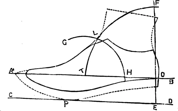
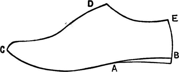
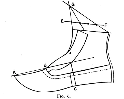
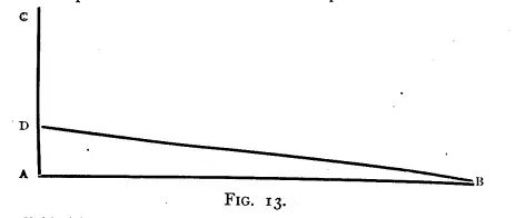
Explained beginning on page 25.
Note that this figure isn’t accurately drawn according to the text.
As described:
- Line AB is perpendicular to line EF.
- Line CD, the ground line, is perpendicular to line EF.
- The distance from D to B is the heel height minus the sole thickness.
- The radius of arc TLF is half the heel measure from O.
- The radius of arc GLH is half the distance from T to O.
- Point L marks the middle of the throat.
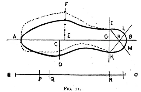
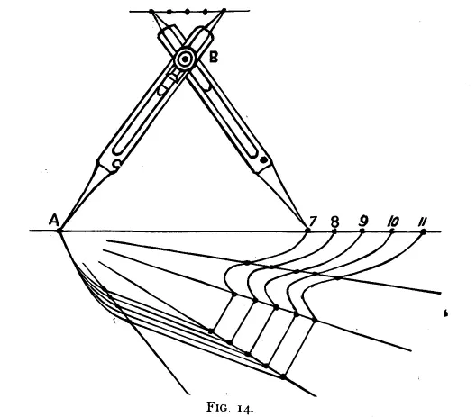
Explanation on Page 25
Do not be frightened at this diagram; it is by no means complicated. You place the form upon a sheet of paper, and mark round it with the pencil; you then add 7⁄10 in. along the bottom for lasting, as shown by the dotted lines. This is for machine-sewn work, with an average lightness of top . If for hand-sewn 4⁄10 in. will do, and if the top be strong or light we have to adapt allowances to the quality. After adding the 7⁄10 in. for lasting we measure from the corner of the heel of the pattern, the height of heel itself, minus the substance of the edge of the sole. To make it clear. Suppose the height of heel the boot designed for is 1 3⁄4 in. and the edge of the sole is 1⁄4 in. in thickness, we measure off 1 1⁄2 in., this gives us the point E. From the point E we draw the line EC, touching the bottom of the pattern at point P. Now from the point O at right angles to the line EC, draw the line EF. Now, I need hardly remark, at this time of day, that the leg is not perpendicular to foot when elevated by the heel, but to ground upon which the heel and toes rest. Now the line CD represents the ground, and if the leg is at right angles to the ground, it must be parallel to the line EF, and so it is; and if we draw a line parallel to EF, in the centre of the leg, it would give us the line by which the inclination of the pattern is regulated; so we see it depends upon the height of heel what inclination we give the leg. But not only does it depend exactly on the right inclination we give the leg, but we must find also what position would be the right point from which to start the front of leg at throat of pattern. For if we begin the leg too far back, we would make the back seam almost straight, and then we would be compelled to choke the pattern at the throat; so we want to find a starting-point. To find this , we draw a line from the point O parallel to CD, and from the point O, with a radius of half the heel measure, we describe the arc TLF, and from the centre T, with a radius of half the line TO, that is, quarter the heel measure, describe the arc HLG. And where the arcs cross each other is the correct point or middle of the throat. Now, with a starting-point found, and the inclination to guide us, it is not very hard to draw the front of leg by the curve from the point L; then, with the leg measure to serve as a help, the remainder of the back seam is easily completed.

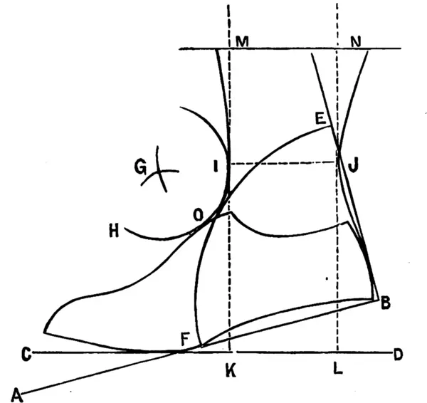
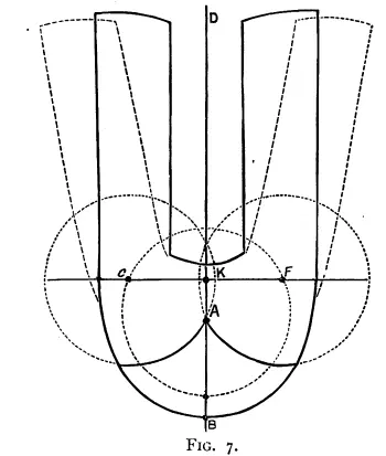
Explained beginning on page 31.
Note: per the author, “not over accurately drawn”
The distance from K to L is half the ankle measure.
Line AB is perpendicular to line BE.
The radius of arc FOE is half the heel measure from B.
The distances from F to G and E to G are half the heel measure.
The width added to the topline ahead of M is ¼ of ¼ of the length of line IJ.
The width added to the topline behind N is ¾ of ¼ of the length of line IJ.
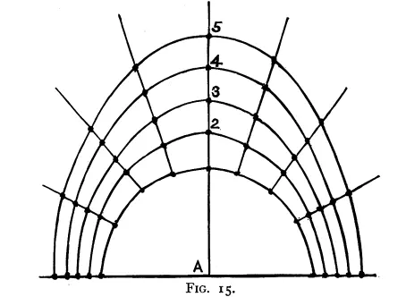
Explanation Beginning on Page 31
The form being obtained as described, place it upon a sheet of paper, and mark round with a fine-pointed pencil; draw the line BE from the corner of heel and passing through the back of the form, as shown in the diagram. From B draw at right angles the line BF, then from B, as centre at a radius of half the heel-measure, describe quadrant FOE. From the extremities of this arc F and E, for centres using the same radius, describe arcs, cutting each other at G; now, from G as centre, and radius GO, make the arc ΗΟΙ. This will connect the form of the leg (yet to be constructed) in a circular curve, thereby making a correct pitch, which, as I said before, is not changed by any variation in the height of heel, for it is the stationary hinge upon which the leg is rotated, either backwards or forwards, being entirely governed by the heel-measure, and the angle it makes with the bottom of the foot.
To get the correct inclination from a given height of heel, we proceed thus: &emdash;Measure from the corner of heel, point B, the height of heel the pattern is to be designed for, minus the thickness of sole, and at that distance from B draw the line CD, passing through the ball F. This is the ground-line. Now from this draw a perpendicular KM tangent to (touching) the arc HOI; from K set off half the ankle measure along CD to L, and from L erect another perpendicular, LN. Now we have the main structure for the leg, as seen by the dotted parallel lines KM and NL being the foundation upon which the inclination and leg-curves depend. The rule for calf measure, after making up statistics compiled from average measurements and examination of the best models, I find is this: that if the calf measure be located at a distance of half the ankle from the ankle-line itself (IJ), its increase over the ankle measure is one-fourth of that ankle-measure. Now, to apply this rule, based upon normal proportions. Join IJ, which is the ankle measurement, because IJ is equal to KL. From I set off along KM the distance IJ. This will be as far as M. From M draw the horizontal line MN. Now, according to our rule, we have to add one-fourth of IJ to MN. The question arises, where shall we add this increase? Is it to be placed at the side M, or N, or half-and-half-perhaps some would say all at the side N. This will depend upon the particular idea of the pattern-cutter. If he wants the leg to hang back, he would apply, not only all the addition at N, but also take some from M and add it to N. If the front line is required to be perpendicular, the increase is simply added at N. But in reality there is only one way to apply this addition, and that is the right way. It will be remembered I said the front of the natural leg was not at right angles to the ground, but slightly inclined forward, and that the pattern required to be more so. So what we do is this: Divide the increase in four parts, add three at N, and one at M. This is about the proper proportion and right inclination. The formation of the curves will present no difficulty. Join the points thus found to I and J in a graceful outline, and connect the back of the form in a continuous curve to J. Add 5⁄8 in. lasting in light work, machine-sewn, and 7⁄10 in. for strong work, along the bottom. Complete by cutting out in a graceful form a correct standard through the fixed points obtained. I may remark that in some scales of fittings, especially if the heel or ankle measure is above or below the average proportion, that the arc HOI may not catch the top of the form. Should such be the case this slight irregularity must be finished freehand, keeping outside the larger ones to prevent any radical mistake. This system may appear complex and roundabout, but in practice it is nothing of the sort. Once it is understood it is sure to be easy, automatic, and correct. …
III. Principles of Design
[almost entirely a theoretical or philosophical chapter]
-
Competition is a foster-parent given to man for his guidance and protection…
- comfort, attractiveness, utility
-
Never speak about anything big in the presence of the fair sex, or you may make an enemy for life.
- “Wurtemburg heel”
-
More people have died by unsanitary boots than people are aware of, or care to inquire about.
- extremely pointed toes under Richard II, extremely broad toes under Henry VIII
- straight lasts coming back in fashion in France
- beauty
- proportion
- symmetry
- utility
- perfection
- decorative art or ornamentation
- Venus de Medici: 5’2” tall, 9” foot]
-
proportion is often odd, whereas symmetry is always even
-
Or, as “Heaven helps those who help themselves,” let the shoemaker himself start the racket, and the support that ought to come, will and must come. We are too much content with supplying the demand: why not cause an extra demand by beginning supply?
-
we must remember that what might please the “upper ten” is often contemptible with the “lower orders.”
-
Any residue of the “tinsel age” should be erased.
- “seam-to-toe”
-
Always put a lighter colour in the legs of your upper than in the vamps or foxings, if you want your contrast to prove effective. With black materials place the dull colour also in the leg, while glazed enamelled or polished stuff surrounds the remainder.
- Hogarth’s “line of beauty and grace”
- Polygraph designs [like a modern Spirograph]
IV. Practical Designing
- vamp height
- general rule: “low enough to go on easily, and high enough to look well”
- average: one third length of standard
- shorter for ladies on high Wurtemburg heels
-
One-eighth inch or one-fourth inch above or below this makes very little difference…
- too low
- unsightly
- can slip on lasting
- too high
- hard to take on and off
- burst on lasting or treeing
- vamp length
- usually double AB
-
the wing of vamp is usually the same length as height of vamp
-
The depth or width of wing is one-third the width of vamp, i.e., each wing is one-third, and the space between them another one-third.
-
it is always well to have gol quarter never lower at back than front, for if otherwise an awkward seam comes upon a very tender part of the heel, besides it looks far from stylish
- adjustments
- add quarter inch up front seam and back seam
- for seaming
- cut half inch from top of leg
- will be covered by top band
- prevents frayed edge at top
- add quarter inch up front seam and back seam
- mistake to use same pattern for lining
- no spring at all
- quarter inch difference between outside and inside leg quarters of button boots
- usual seam allowances
- sixteenth inch for light material
- eighth inch for heavy
- quarter inch for woven fabrics, overlaying 3/8
-
The front of all quarters or legs (at B, Fig. 6) should contain a little extra allowance for contraction in maching.
-
For lasting ¼ in. is sufficient for hand-sewn, and ⅝ in. for all other sorts of work.
-
The designer must always keep three things in view when cutting any style of pattern—first, its utility, second, its beauty, and third, its economy.
-
Utility must not be sacrificed for beauty, nor beauty for economy.
- good economy
- extreme bottom corners of vamps, since lasted away
- vamps and straight toe caps as separate pieces, not overlapping [false toe caps]
-
also enables a pointed last to throw off a better shaped toe, as there is not so much bulky stuff at this spot
-
Some bespoke masters have a piece of inferior stuff whipped to the vamp in place of the portion cut off.
-
Every clicker knows that it is the peak fo the toe and the projecting corners of lining patterns that cause all the waste in cutting.
-
-
Shoe linings should be divided in like manner, and not have the seam at the usual and very bad spot in a shoe—the back of heel. The seam of the quarters is there, and that is more than enough..
-
Top bands should always be divided at the back seam. They look equally as well as when whole, and are most economical in clicking.
-
A very common blunder I see in a vast amount of work is that side-springs are inclined forward, and laced boots backward. This is decidedly wrong.
- button boots get shorter vamps than Balmorals, since harder to get foot in and out
- “Lorne shoe”
-
The tabs of a Derby pattern should be situated two-thirds the length of the whole from the back seam.
- don’t round tabs of Bluchers, Derbys, Lorne shoes
-
The majority of the usual designs can be changed into different patterns by a few slight alterations.
- Derby to Navvy:
- quarters whole back
- straight tops
-
tabs elongated into peaks almost coming to the toe
- add water-tight tongue
- tongue at top: heel measure minus ankle
-
The machinist in attaching the quarter and tongue to vamp has to pull this slit very open to make it fit on the vamp, which actions throws a permanent spring into the tongue, and causes it to stand up well. No blocking is necessary, and the pattern is rendered very economical in cutting.
-
All water-tight tongues should be closed on top of vamp and not under.
- ordinary straight tongues annoy by failing to stay in place
- stitch to one side at top of facing
- fasten to quarter under last eyelet
-
In pitching whole back boots forward so as to make them sit in well at back, don’t overdo it, for, as the material used in this style of work is generally very heavy and hard, it would be likely to chafe and inflame the leg of the wearer.
- “army rejects”
- shoe patterns
- modify boot patterns
- best to work from last instead
- 1832 Henley ploy
- assembled tons of shoemakers
- claim: shoemaker could make six pairs a day with sufficient materials
-
This grand and valuable secret, gentlemen, consists in simply cutting the legs off of boots.
- “seven shoe”
-
Theoretically speaking, all shoes should have inside and outside quarters, so as to fit the ankles properly.
- graduate scallops from bottom to top
- discusses question from City and Guilds of London Institute Examination Paper of 1888 No. 6: “How would you cut a whole golosh pattern?”
- joined gol vamp
- slightly spring the gol wings
- spring so inside edges of gol wings touch at back
- some use the cutout in the middle for boys’ tongues
- slippers should be sprung
-
All the parts of a design have a certain proportion to the length of standard or to themselves.
- method from American Reporter
- divide length in twelve equal parts
- [compare Sabbage’s Sectionizer]
- Ball 2/12
- Instep 4/12
- Heel 6/12
- Ankle 4/12
- Leg 5/12
- Length of Vamp 4/12
- Length of Quarter on Bottom 4/12
- Location of Ball Measure from Toe 3/12
- Location of Instep 6/12
- front leg line perpendicular, starting seven twelfths from toe
-
“Jack” or hunting boots, apparently all in one piece, but in reality having one seam coming down the front of the leg, across the throat, terminating at the inside waist, closed with a flat seam, and completely hidden in ingenious enamelling.
- describes Oxford prize shoe without any visible seams
-
Many of us laughed at the idea of making long work to fit closely around the ankle, yet this is accomplished in an Italian boot by a spring, and by a bellowsed opening in the “Field boot.”
- “Garibaldi”
- method for taking bottom paper from a last
- fasten paper
- trim with scissors
- finish with knife
- laced, button, elastic boots: higher in front of leg than back
- strong lace boots: “full up to measure, and sometimes over at the ankle, and especially at the heel”
-
All tongues should appear half an inch above top of quarters.
- button boot standards 1/16 inch larger in fitting than laced
- elastic designs: make spring as narrow as possible
-
As a general rule, the width of gore is quarter of the whole ankle circumference.
- method: measuring tape from back of heel over the toe
-
If anything, have your standard quite dead, for no laster can fully eradicate the pleats round the upper which eminate from an excessively sprung pattern, especially when working on a spite-toed last with such material as crup or enamelled leather.
-
Never peak the bottom corner of heel by hollowing the waist…
-
A great number of cutters advocate that the end of wing of vamp and side seams in all work should come in the waist of pattern (bottom of instep), or halfway between heel and toe of standard.
-
Take in all the trade journals that you can afford to buy and read.
-
“I have learned enough to know how little I do know.”
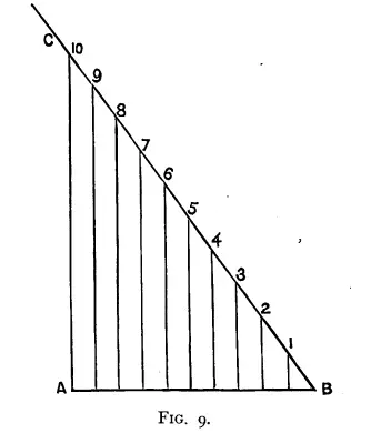
V. Regular Gradation
The numerous methods of for graduating.–Repeated construction.–Arithmetic fractions.–How to compile a correct and complete scale of fittings.–Simple and useful method of grading.–American process.
- “complete sets” [standard patterns graded in all sizes]
-
the proportional or mechanical system, which may be said to condemn all others to oblivion
- in past, didn’t use any rule
-
Each pattern was specially and separately designed for every size last.
- fractions
- “amount of grade”:
the difference between the measurements of one foot, last, or pattern, and those of another a size larger or smaller
-
amount of grade less at heel thank ankle
-
instep: 1/4 inch
-
Others think it greater in the large sizes than in the small ones ; but the variation, if it exists, is so little we cannot practically find it, unless by the geometrical system.
- cacks: bit less than 1/4
- largest mens: a bit more than 1/4
-
for the whole circumference
- affected by width of sole
-
-
ankle 1/4 inch, “or a trifle less”
-
heel about 1/3 inch
-
ball 3/16 inch
-
length 1/3 inch
-
the majority of lastmakers applied an unvarying ¼in. to the circumference of the joints and insteps of their lasts, used a method of gradation for the standard pattern known as the “eighths” system, applied in this manner.
-
“frontseam”
-
“cross-top”
-
“the one-sixteenth all round system”
-
“shifting process” by Airedale in The Boot and Shoe Trades’ Journal
-
“Hannibal’s system” from Last-Fitting and Pattern-Cutting
-
foot measurement tables from trade journals
- C.F. Alden
- Gustav Pabst
- Shoe Dealers’ Associations of America
- The Shoe and Leather Record “Students’ Column”
- Airedale’s in Boot and Shoe Trades' Journal
-
-
joint and instep measures are intended for the last, while the heel and ankle measures are applied to the pattern
-
-
infants’ size graded by unproportional system
-
Take an average full foot and you will find that the difference between the joint and instep is very little. Measure a slender foot of the same length, and the disparity between the joint and instep circumference will be most glaring.
-
-
Fitting 1 Fitting 2 Fitting 3 Fitting 4 Fitting 5 8⁄9 in. 7⁄9 in 2⁄3 in. 5⁄9 in. 4⁄9 in. -
Many advocate that the gradation of these fittings be scaled in each size by 2⁄9 in. at joint and instep; but it will be better to apply the geometrical system of grading.
-
-
Dodge’s system
-
best possible substitute
- place smallest size inside largest, divide difference by number of sizes between and distribute evenly
- can grade all pattern pieces
- drawback: have to make the extremes by hand
-
-
Stacked Bevels Method
- trace onto pasteboards
- pile together, bind with tacks
- whittle beveled edges
- separate, cut off the bevels, squaring the edges
-
neither easy nor practical to anyone but a full-fledged adept in the process
VI. Mechanical Grading
The property of the triangle.—Explanation of geometric grading.—Grading tools.—Use of mathematical instruments.—The proportional compass.—Universal system applicable to all patterns.—Unproportional grading applicable to various countries.
- names:
- geometrical system
- proportion system
- mechanical system
- based on similar triangles
-
fallacy of applying an unvarying addition all round an irregular figure
- “strict proportion”
-
a set of standard patterns—sevens to tens
- method
- pick point within standard
- draw lines radiating out to key points
- proportional dividers
- list of tools
- drawing board
- t-square
- paper
- pencils
- drawing pins
- set squares
- compass
- dividers
- bow pen compass
- pencil compass
- ruling pen
- protractor
- “military casters”
-
The use of the parallel rule or set-squares is called the geometrical system, the grader or tool the proportional system, the proportional compasses the mechanical system, and the following modification the unproportional system…

VII. Appendix
Bespoke work.—Improved system of measurement.—Last fitting.—Cutting to irregular measures.—Long work.—Metallic patterns.—Systematic arrangement of working patterns.
-
the best man in the world is sure to make many misfits at times
-
I never made a mistake yet that I could not attribute either to carelessness or haste.
-
…I have an advantage… I generally take the measure, fit up the last, and cut the uppers myself.
-
foot measurement
- measure clients “away from the vulgar gaze”
-
ladies, who often desire to wear shoes shorter than their feet
-
Suppose you call out 6’s, and she exclaims, with a horrified expression on her face, that she positively never wears more than 4’s, give way at once ; but you know what to do afterwards.
-
Should you, in measuring both feet, happen to observe that her right is larger than the left, excuse yourself directly, and you may be forgiven by her only indignantly gasping “No, sir ; if you knew but all, it is the left that is smaller than the right.”
-
After criticising every system of measurement…there is nothing better than the ordinary inch tape and the use of a few symbolic marks.
- marks
- flat line for flat insteps
- concave line for arched insteps
- slanted line for hoof-like feet
- bunion with circle
- asterisk for corn
- choose nearest stock last
-
two straps fastened together at right angles
- [perpendicular tape measure]
- over the big toe
- lead weight on end to drape over toe
- since ordinary tape measure only marked in eighths, use T and F for tight and full
- “conspicuously abnormal” feet: use cardboard for plan and elevation foot tracings
- blocks of wood for different heel heights
- foot impression method
- describes dimensionless tape measures
-
girths
- joints:
- “fair tension”
- note whether angled or straight
- instep
- mark location
- heel measure
-
if not taken while the foot is flexed (not in a state of rest), it will be too small
-
- ankle
-
at the small part of the leg, just above the ankle joint
- slack, not tight
-
- leg girths
- carefully locate
- always measure both feet
- joints:
- modifications
- length
- men’s: 3 sizes
- women’s 2½
- boys’ or girls: 2
- children: 1½
-
Some people cannot bear the slightest pressure on their feet. I have known others to squeeze their feet into so small a space as to surpass belief.
- depends on material
-
A hard, angular foot, generally said to be bony, having joints and projections fully marked, will stand little or no pressure.
-
This is generally the characteristic of men’s feet.
-
A lady’s foot is generally round and soft, and like a sponge, capable of being compressed into small compass, having the joints and other angular points fully protected by a bountiful supply of flesh, acting as an elastic pad or cushion.
-
both men and women will have characteristics the very reverse of these
- factors
- fine and elastic or heavy unyielding upper
- fleshy, soft, bony, or hard foot
- length
-
last fitting
-
location of the girths as measured from the toe is different on the last than on the foot
- leather for last build-up best from insole bellies, about ⅛ in thick
- wet, block while mellow, allow to dry
- can also use waxed calf neck
- three key shapes
-
full leather covering the instep and toes making the last larger all through
-
instep leather, only going a little below the cone of instep
-
toe leather
-
- three sets of each size
- bunion pieces
- egg-shaped
-
place half upon the inside of the joint, and the remainder upon the sole of the last
- “heel-pin”
- stout kip works for temporary fittings
- paste fittings on, then peg
- iron lasts: gutta-percha, heated, or by soldering
-
-
patterning
-
In cutting patterns to measure, rules and proportions are but of secondary use. All our little schemes which hold the field in the wholesale trade are knocked out of time in the bespoke trade; when backed against practical experience, the educated eye being always triumphant, and the ability to judge by the brain predominant when called upon to meet the requirements of irregular measurements.
-
when I receive measures by post from persons outside the trade, I always find it better to cut to the regular scale if there is not much disparity between them, because it is better to chance the usual measurement than depend upon the uncertainty of an amateur
- additions to the ankles change pitch and inclination
- side elevation best to show peculiarities
- make copy of original standard to cut into pattern pieces, preserving the original standard for future work
- long work
-
A great quantity of this class of work is cut at the present day by the extolled “jockey-closer,” who generally cuts direct from the leather, taking little or no help from one or two patterns which he jealously keeps from the prying eyes of those are “not in the know.”
- “Clarence” boot
-
the important thing that has to be calculated, is to secure the free passage of the foot into the boot [the pass]
-
the ankle portion must almost equal the heel measure
-
the heel is larger than the ankle
-
when the foot is half way down the leg, it is the low instep and not the throat of his foot that presses against the front of the boot, while the tip of his heel is in contact with the back-seam
- variation: high, immobile instep or great range of motion
-
It was fashionable at one time to have the portions of back-seam from D to F [along the back of the calf] come out in a great swell, but in high-class work no curvature is permissible. The popular wish at the present time is to have this portion perfectly straight.
-
the foot will enter the lower portion of boot with a sudden jerk
-
To give the boot a natural sit, we have to cut out a gore piece at what would be the bend of the knee.
-
-
-
clicking
-
Wood, leather, cardboard, tin, zinc, sheet-iron, &c., have ben used for working patterns ; but the only two materials which hold their own as yet are No. 15 zinc or strawboard (afterwards bound with brass).
- hammer zinc over wood block
- file off sharp edges and smooth with emery paper
-
Through a miscalculation, I am brought to rather an abrupt close…